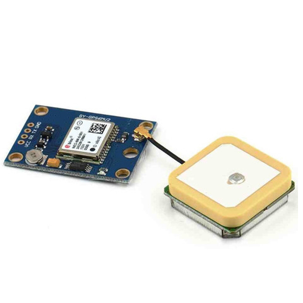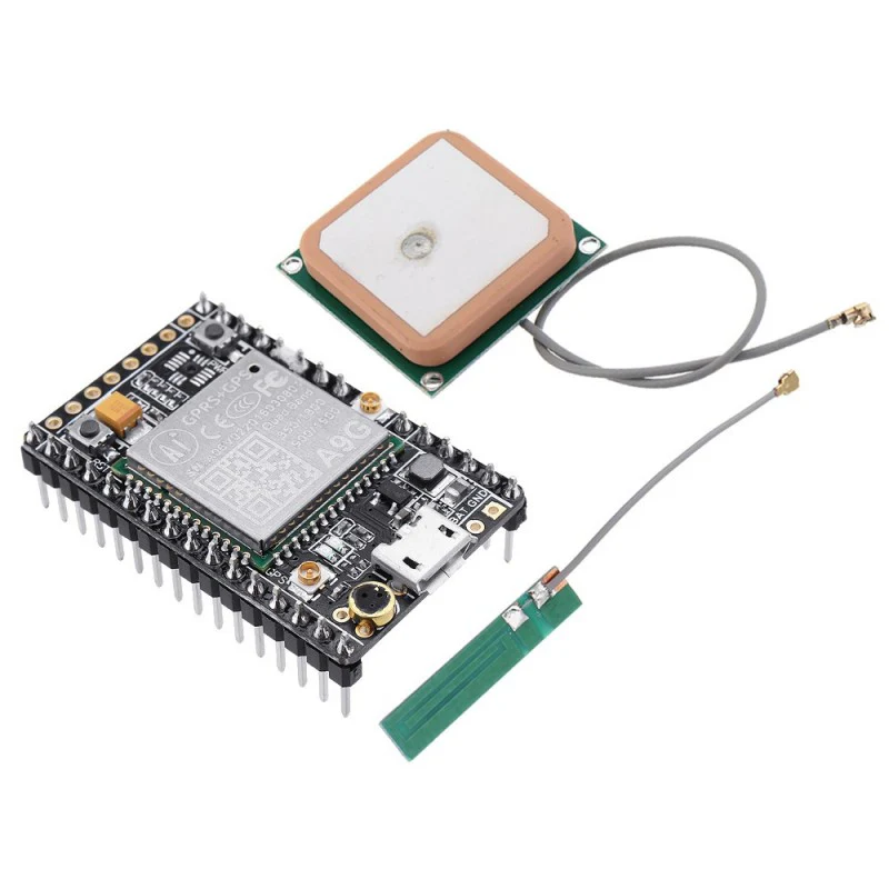
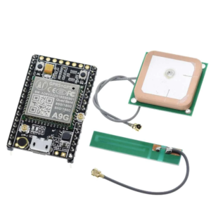
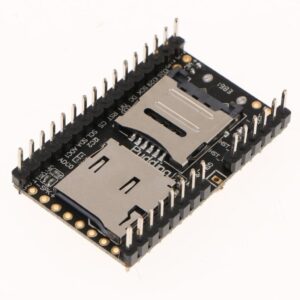
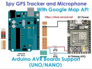
Ai-Thinker A9G GSM/GPRS+GPS/BDS Development Board
In Stock
Categories: Modules, Ethernet, Other Modules, Wireless
Overview
Description
Ai-Thinker A9G GSM/GPRS+GPS/BDS Development Board – Powerful IoT & GPS Solution
The Ai-Thinker A9G GSM/GPRS+GPS/BDS Development Board is a compact, feature-rich development platform designed for engineers, students, makers, and IoT enthusiasts who want to create wireless communication and location-based applications with ease. This module combines GSM/GPRS connectivity with GPS and BDS (BeiDou Navigation Satellite System) positioning, making it an excellent choice for real-time tracking, data logging, and remote control projects.
Whether you’re building a GPS tracker, smart vehicle monitoring system, IoT sensor node, or any project that requires both cellular communication and global positioning, the A9G development board offers a cost-effective and reliable solution.
Key Features of Ai-Thinker A9G GSM/GPRS+GPS/BDS Development Board
-
Dual Functionality – GSM/GPRS + GPS/BDS
-
The A9G integrates both GSM/GPRS for data communication and GPS/BDS for accurate positioning.
-
Supports 2G quad-band (850/900/1800/1900 MHz), making it globally compatible.
-
Provides real-time GPS tracking with high precision for navigation and IoT applications.
-
-
Compact and Lightweight Design
-
Small form factor, ideal for portable devices.
-
Perfect for integration into DIY projects, smart devices, and embedded applications.
-
-
Low Power Consumption
-
Designed with IoT in mind, it consumes minimal energy during standby and active modes.
-
Great for battery-powered devices like trackers and remote sensors.
-
-
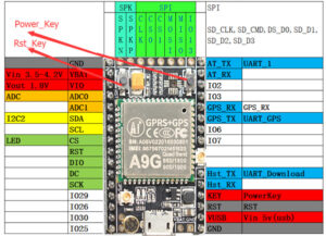
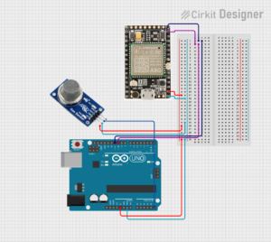
Multiple Interfaces for Development
-
UART, GPIO, ADC, PWM, and I²C interfaces available.
-
Allows easy connection with sensors, microcontrollers, and external modules.
-
-
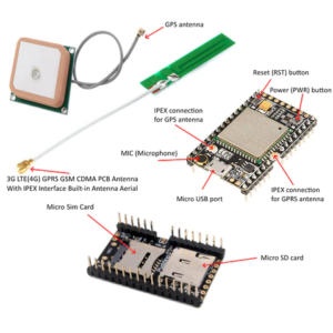
Onboard Antennas and Expansion
-
Supports external GSM and GPS antennas for better signal reception.
-
Expansion pins for flexible prototyping and customization.
-
-
Wide Range of Applications
-
GPS trackers for vehicles, pets, and assets.
-
Smart agriculture and environmental monitoring.
-
IoT smart home projects.
-
Remote data collection and reporting systems.
-
Why Choose Ai-Thinker A9G Development Board?
The A9G board stands out due to its integration of GSM/GPRS connectivity with GPS/BDS navigation, giving developers a single solution for communication and tracking. Unlike traditional modules that require separate GSM and GPS chips, this compact development board reduces cost, simplifies design, and saves space.
-
Reliability: Stable communication with strong GPS signal acquisition.
-
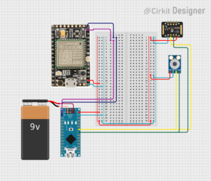
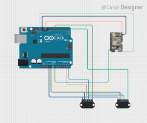
Flexibility: Multiple I/O options to connect to Arduino, ESP32, Raspberry Pi, and other development boards.
-
Cost-Effective: Affordable compared to similar modules with dual GSM+GPS functionality.
-
Community Support: Widely used in IoT projects, so finding tutorials, code examples, and libraries is easy.
Technical Specifications
-
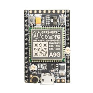
Module: Ai-Thinker A9G
-
Network: GSM/GPRS, Quad-Band (850/900/1800/1900 MHz)
-
Positioning: GPS + BDS support
-
Power Supply: 3.4V – 4.2V (typical 3.8V)
-
Interfaces: UART, I²C, ADC, GPIO, PWM
-
Antenna: External GSM and GPS antenna support
-
Working Temperature: -40°C to +85°C
-
Dimensions: Compact design for embedded applications
Applications of Ai-Thinker A9G GSM/GPRS+GPS/BDS Board
-
GPS Tracking Systems
-
Vehicle tracking for fleet management.
-
Asset tracking for logistics and supply chain.
-
Personal GPS trackers for safety and outdoor activities.
-
-
Smart IoT Projects
-
Remote weather stations with real-time updates.
-
Smart agriculture sensors with location reporting.
-
Smart city applications like bike or scooter sharing.
-
-
Communication Systems
-
Remote data monitoring via GSM network.
-
IoT devices with SMS or GPRS connectivity.
-
Emergency alert systems with location data.
-
Benefits of Using the Ai-Thinker A9G Development Board
The Ai-Thinker A9G GSM/GPRS+GPS/BDS Development Board offers an excellent balance between performance, size, and affordability. With its dual connectivity features, you can easily combine cellular communication with real-time GPS positioning in a single device. This makes it highly practical for a wide range of projects, from simple hobby electronics to advanced IoT tracking devices.
Developers appreciate its low power consumption, which makes it perfect for portable and battery-powered applications. Students and makers find it user-friendly and well-documented, while companies use it for creating smart monitoring systems, GPS tracker boards, and IoT communication solutions.
Whether you are building a GSM GPRS GPS development board project, a location-based IoT device, or experimenting with embedded systems, the Ai-Thinker A9G module provides the flexibility and reliability you need.
Conclusion
The Ai-Thinker A9G GSM/GPRS+GPS/BDS Development Board is a powerful and affordable platform that bridges the gap between cellular communication and satellite-based positioning. Its versatility makes it suitable for a wide range of applications, from GPS trackers and IoT projects to smart monitoring systems.
If you’re looking for a compact, energy-efficient, and cost-effective solution for real-time tracking and GSM communication, the Ai-Thinker A9G Development Board is the perfect choice.
👉 Order your Ai-Thinker A9G GSM/GPRS+GPS/BDS Development Board today and start building your next IoT innovation!
Customer Reviews
Based on 0 reviews
0
Verified Purchases
0
Reviews with Photos
0%
Would Recommend
Sign in to write a review
Sign InNo reviews yet
Be the first to review this product.