KY039 Finger Detection Heartbeat Measuring Sensor Module
Out of Stock
Categories: Modules, Sensors, Medical Sensors, Other Modules
Overview
The KY-039 Heartbeat Sensor Module is a photoplethysmography (PPG)-based sensor designed to detect heartbeat/pulse signals by measuring blood flow changes in fingertips or earlobes. This low-cost module uses an infrared (IR) LED and phototransistor to capture pulse waveforms, making it ideal for health monitoring, fitness tracking, and biomedical projects.
With simple analog output compatibility, the KY-039 can interface with Arduino, Raspberry Pi, and other microcontrollers to visualize real-time pulse data or trigger alerts.
Description
Heartbeat Sensor Module KY039
-
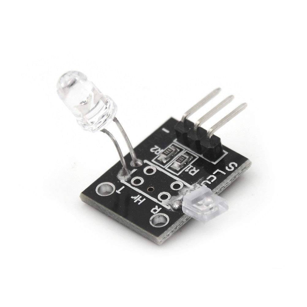
The Heartbeat Sensor Module KY039 is designed to detect a pulse while a human finger is place between the infrared diode and the photo transistor. The pulse will be represented on the signal output pin.
- This sensor works by using a photo transistor to detect the presence of light, in this case how much light is passing through a finger. When blood moves, the amount of light changes and that change can be detected as a pulse.
- This project uses bright infrared (IR) LED and a phototransistor to detect the pulse of the finger, a red LED flashes with each pulse.
- Pulse monitor works as follows: The LED is the light side of the finger, and phototransistor on the other side of the finger, phototransistor used to obtain the flux emitted, when the blood pressure pulse by the finger when the resistance of the phototransistor will be slight changed.
- We chose a very high resistance resistor R1, because most of the light through the finger is absorbed, it is desirable phototransistor sensitive enough. Resistance can be selected by experiment to get the best results.
- The most important is to keep the shield stray light into the phototransistor. For home lighting that is particularly important because the lights at home mostly based 50HZ or 60HZ fluctuate, so faint heartbeat will add considerable noise.
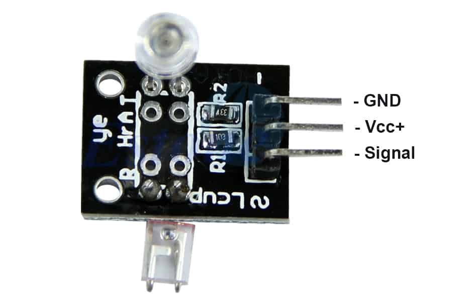
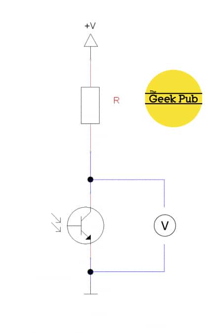
DEVICE PINOUT & SCHEMATICS:
- This module has three pins: GND, Vcc , and Signal. The pinout is as follows:
- The KY-039 heartbeat sensor schematic is as follows:
CODE EXAMPLES:
- Youll find below code examples of using the KY-039 heartbeat sensor with both Arduino
-
KY-039 HEARTBEAT SENSOR CODE EXAMPLE FOR ARDUINO
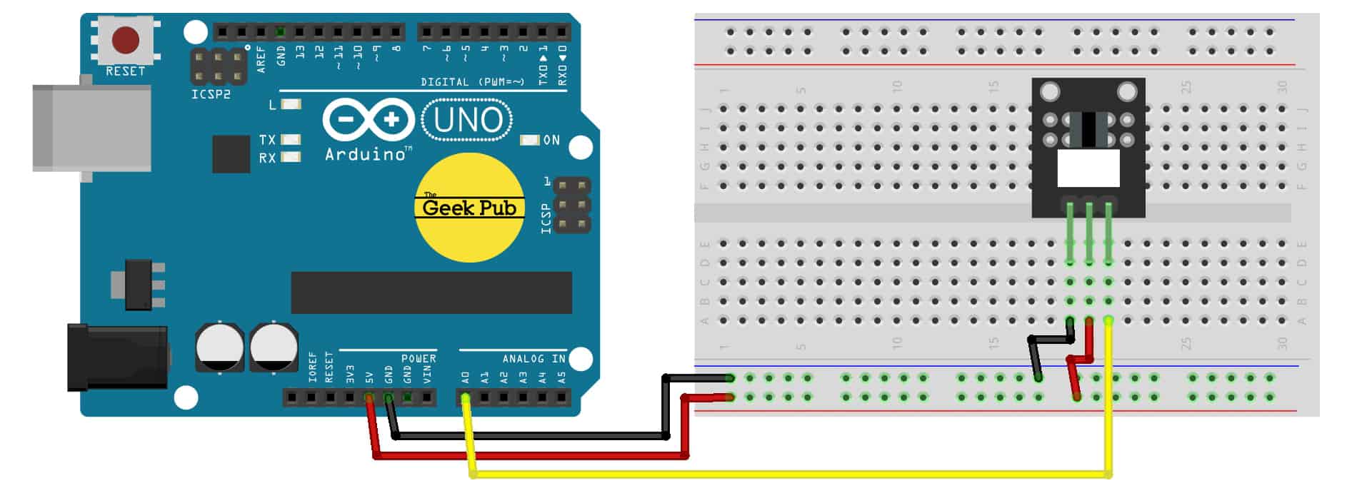
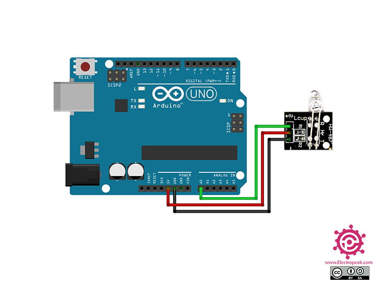
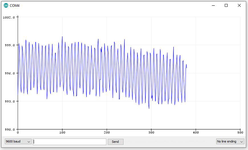
The following code example is for the Arduino. This code will read the Analog Output Sensor value and write it to the serial console, pause 500ms and repeat.ARDUINO WIRING:
- KY-039 Sensor GND to Arduino GND
- KY-039 Sensor Signal to Arduino PIN A0
- KY-039 Sensor Vcc to Arduino 5V
 1234567891011121314151617181920212223242526272829303132333435363738394041
intledPin=13;intanalogPin=0;voidsetup(){// The included LED of the Arduino (Digital 13), will be used as output here.pinMode(ledPin,OUTPUT);// Serial output initializationSerial.begin(9600);Serial.println("Heartbeat detection example code");}constintdelayMsec = 60;// 100msec per sample// The main program has two tasks:// - The LED will light up after detecting a heart beat// - Calculating of the pulse and outputting of it at the serial out.voidloop(){staticintbeatMsec = 0;intheartRateBPM = 0;Serial.println(rawValue);if(heartbeatDetected(analogPin, delayMsec)) {heartRateBPM = 60000 / beatMsec;// LED-output for the heart beat heart beatdigitalWrite(ledPin,1);// Output of the serial dataSerial.print(rawValue);Serial.print(", ");Serial.println(heartRateBPM);beatMsec = 0;}else{digitalWrite(ledPin,0);}delay(delayMsec);beatMsec = delayMsec;}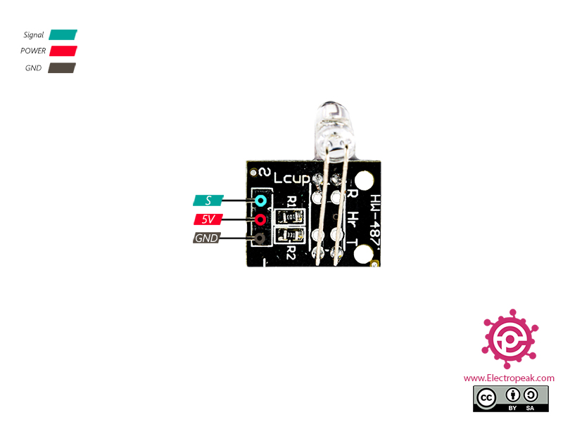
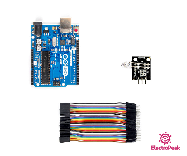

- 1 X Finger Measuring Heartbeat Sensor Module


 Heartbeat Sensor Module KY039
 Heartbeat Sensor Module KY039
Customer Reviews
Based on 0 reviews
0
Verified Purchases
0
Reviews with Photos
0%
Would Recommend
Sign in to write a review
Sign InNo reviews yet
Be the first to review this product.