


Pulse Induction Metal Detector – Digital Output – Single Channel
Original price was: 3,000.00 EGP.2,500.00 EGPCurrent price is: 2,500.00 EGP.
This Pulse Induction (PI) Metal Detector Sensor is a high-performance sensing unit
designed for robust and accurate metal detection across a wide range of
environments. Engineered for both professional and hobbyist applications, this sensor
features advanced detection capability, flexible calibration, and multiple built-in
protection and signaling features.
Description
Pulse Induction Metal Detector – Digital Output – Single Channel
High-Sensitivity Metal Detection Sensor – With Flexible Calibration Settings
Key Features:
-
⚙️ User-Adjustable Calibration Controls
Fine-tune sensitivity and detection thresholds with ease. Supports multiple custom detection coil configurations thanks to flexible calibration options. -
🔄 Input Reverse Polarity Protection
Prevents damage to the sensor and connected circuits if the power supply is connected with reversed polarity. -
⚡ Output Short Circuit Protection
Built-in protection for the output driver circuit against accidental short circuits, ensuring long-term safety and reliability. -
💡 Digital LED Indicators
-
Power LED: Indicates the sensor is properly powered.
-
Detection LED: Lights up when a metallic object is detected.
-
-
🔊 Audible Buzzer Output
Provides a clear audio alert upon metal detection — ideal for use in noisy or low-visibility environments. -
🌙 Low Power Sleep Mode
Digital enable/disable input allows the sensor to enter ultra-low power mode when not in use. -
📏 Compact and Durable Design
Optimized for integration into portable or embedded systems with a robust layout.
Technical Specifications:
-
Input Supply Voltage Range: 6V – 32V
-
Nominal Supply Voltage: 12V
-
Current Consumption @12V:
-
Normal Operation: 110mA
-
Sleep Mode: 0.5mA
-
-
Default Detection Coil Parameters:
-
Inductance: 1.1 mH
-
Resistance: 2.5 Ohm
(Supports other custom coils via calibration)
-
-
Board Dimensions:
-
PCB Only: 80mm × 58mm
-
PCB + Terminal Block: 88.6mm × 58mm
-
PCB + Terminal Block + Plugs: 108mm × 58mm
-
Calibration Steps for Maximum Detection Distance:
-
Make sure the sensor is fixed in its working environment, powered on, and connected to the detection coil. Calibration must be done in the actual operating environment.
-
Rotate the Distance Potentiometer fully clockwise.
-
Rotate the Sensitivity Potentiometer counterclockwise until the detection LED turns on.
-
Rotate the Sensitivity Potentiometer slowly clockwise until the detection LED turns off.
-
Rotate the Distance Potentiometer counterclockwise until the detection LED turns on.
-
Rotate the Distance Potentiometer slowly clockwise again until the LED turns off.
💡 Tip: To decrease the overall sensitivity, rotate either the Sensitivity or Distance potentiometers clockwise.
Related products
-
- Sale!
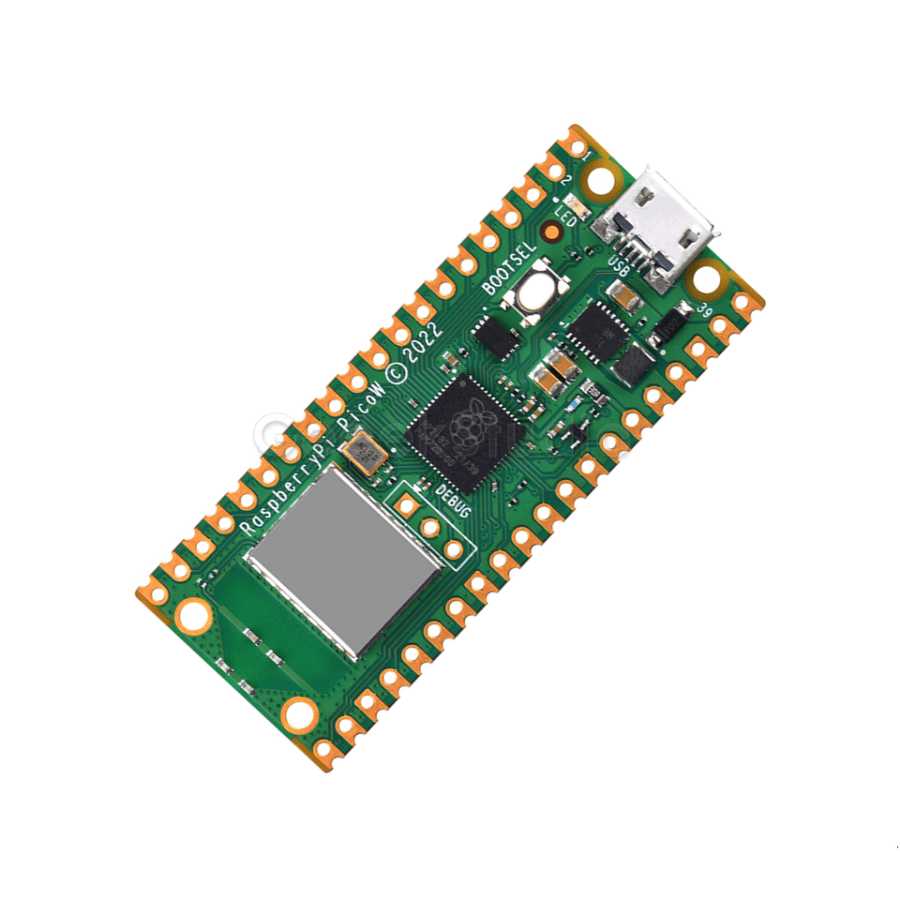
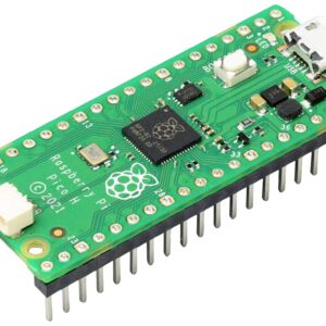
- Developments Boards, Raspberry Pi
Raspberry Pi Pico W Microcontroller Development Board
- Original price was: 800.00 EGP.650.00 EGPCurrent price is: 650.00 EGP.
- Add to cart
-
- Out of StockSale!
- Developments Boards
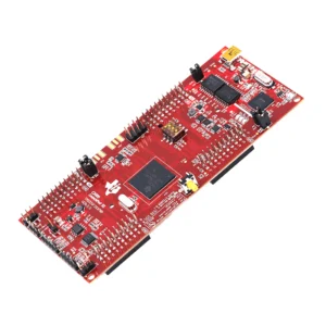
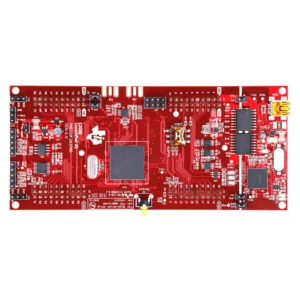
Texas Instruments LAUNCHXL-F28379D – C2000 Delfino MCUs F28379D LaunchPad Development Kit
- Original price was: 6,000.00 EGP.5,500.00 EGPCurrent price is: 5,500.00 EGP.
- Read more
-
Reviews
There are no reviews yet.