Light Sensitive LDR Relay Module 12V
80.00 EGP
Description
Light Sensitive LDR Relay Module 12V
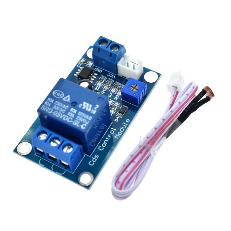
- This module can be used for light detection, brightness detection by utilizing the photoresistor to trigger the 12V relay.
- The sensitivity of the photoresistor can be set by the onboard trimpot.
- This module is great for various projects such as automated lighting, opening/closing of blinds, or any project that is light based.
KEY FEATURES OF LIGHT SENSITIVE LDR RELAY MODULE 12V:
- Automatically controls the relay based on light intensity
- Included LDR (Light Dependent Resistor) sensor on 10″ lead detects visible light
- Adjustable light level set-point
- Controls loads of 115/230VAC @ 10A
- Controls loads of 0 – 15VDC @ 10A
- Both NO (Normally Open) and NC (Normally Closed) contacts
- LED indicator when relay is energized
- 12V power operation
Light Sensitive LDR Relay Module 12V
- This is a self-contained switching module that energizes / de-energizes a relay based on the the detection of visible light.
- Just add 12V power and hook up the load you want to control then adjust the potentiometer to set the brightness level at which you want the relay to switch between ON / OFF.
- This type of module can be used for applications such as to automatically turning a light on when the ambient brightness goes below a preset level as might be the case for a outside security light or night light. It can also detect a flame under some conditions.
- The LDR sensor is attached to a 10″ lead for remote mounting. The lead can be spliced to increase its length if desired.
Theory of Operation:
- The light sensor on the module is a light sensitive resistor (LDR) .
- The brightness level trip-point for triggering the relay can be adjusted using the potentiometer on the module. Turning the pot CW increases the brightness trip-point.
- When the brightness goes below the trip-point value, an LM393 voltage comparator IC energizes the relay and it switches ON. A blue LED is illuminated when the relay is energized.
- When the brightness increases above the preset value, the relay switches back OFF.
- The relay has both NO (Normally Open) and NC (Normally Closed) contacts so the module can either be used to energize a load when brightness goes up past the trip-point value or when it goes down below that level.
- A flyback diode is included on the module in parallel to the relay coil to safely shunt current when the relay coil is de-energized. The module also has a reverse polarity protection diode on the 12V power input.
Module Connections:
POWER
- The module requires 12V power and ground to operate. There is a red LED that is lit when power is applied to the module.
- When the relay is de-energized it draws approximately 10mA. When energized, the module draws about 40mA from the Vcc pin.
1 x 2 Screw Terminal (Power Connections)
- Vcc = Connect to 12V power supply
- GND = Connect to ground of the 12V power supply
LOAD
- The output of the relay is rated to switch up to 30VDC at 10A or up to 250VAC at up to 10A (See our notes below).
- The output is SPDT type with both a NO (Normally Open) terminal and a NC (Normally Closed) terminal relative to the COM terminal.
- When the relay is de-energized (blue LED OFF) the NO-COM connection is open and the NC-COM connection is shorted.
- When the relay is energized (blue LED ON) the NO – COM connection is shorted and the NC-COM connection is open.
1 x 3 Screw Terminal (Load Connections)
- Top = Normally Open relay contact – Load is connected to this terminal if it should switch ON when relay is energized.
- Center = Common connection – Connects to AC or DC power source for load that is being controlled.
- Bottom = Normally Closed relay contact – Load is connected to this terminal if it should switch ON when relay is de-energized.
OUR EVALUATION RESULTS:
- These are nice inexpensive modules that will work for many applications and allow you to control devices based on sensing light without the need to have an MCU involved.
- Just hook up 12V power and your load and you are all set.
- The sensing works over a fairly wide range of light intensities.
- The potentiometer provides a relative rather than absolute setting, so setting the trip point will require some amount of trial and error.
- Positioning of the light sensor will also have an affect on the setting.
- We do find the DC rating of the relay to be too aggressive.
- With DC voltages above about 15V, the contacts can become a little sticky. We recommend using it to switch DC voltages of no more than 15V.
- With AC, the relays performed well in our testing. To test the upper limit we used it to switch a 1500W heater that draws about 12.5A and the relay handled it without any problems.
- To test the device, connect it to 12V.
- While pointing the LDR sensor towards a light source, adjust the pot so that the blue LED just goes off.
- Shielding the LDR from the light should then cause the blue LED to turn on and an audible click heard from the relay as it switches.
BEFORE THEY ARE SHIPPED, THESE MODULES ARE:
- Inspected
- LDR sensor / relay operation verified
- Repackaged in high quality resealable ESD bag for safe storage.
Package Included:
- 1 X Light Controlled Relay 12V Module
- 1 X Photoresistor


Reviews
There are no reviews yet.