7447 DIP BCD To 7-Segment Decoder
18.00 EGP
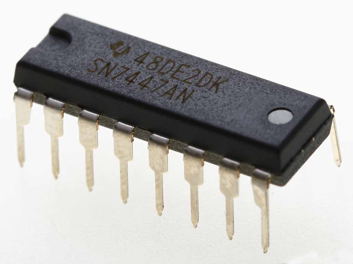
7447 BCD to 7-Segment Decoder/Driver IC – TTL IC with 15V open-collector outputs, ideal for common-anode displays, counters, and digital indicators.
Description
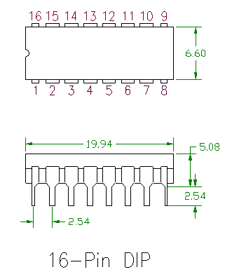
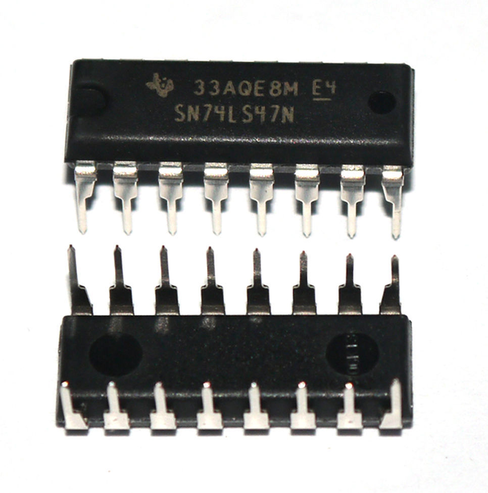
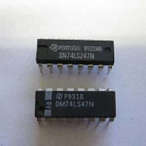
The 7447 BCD to 7-Segment Decoder / Driver is a reliable TTL logic IC designed to convert binary-coded decimal (BCD) inputs into the corresponding 7-segment display outputs. This IC features open-collector outputs rated up to 15V, making it compatible with a wide range of common-anode 7-segment displays and suitable for digital display systems, counters, clocks, and numerical indicators. Housed in a 16-pin Dual Inline Package (DIP), the 7447 is widely used in both educational and professional digital electronics projects.
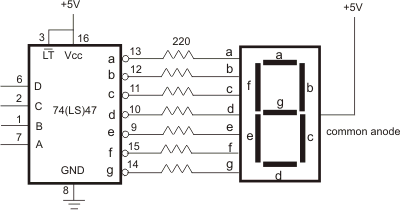
The 7447 simplifies displaying numeric values from a BCD source by directly driving a 7-segment display without additional logic components. It is highly compatible with TTL voltage levels, ensuring seamless integration with other 7400 series ICs, microcontrollers, and digital circuits. Its open-collector outputs allow high-voltage displays or multiple ICs to share a common output line through external pull-up resistors.
⚙️ Key Features:
-
Function: BCD (Binary-Coded Decimal) to 7-segment decoder / driver
-
Logic Family: TTL (Transistor-Transistor Logic)
-
Inputs: 4 BCD inputs (A, B, C, D)
-
Outputs: 7 open-collector outputs (a–g) for 7-segment display
-
Open Collector Outputs: Supports up to 15V, suitable for high-voltage displays
-
Active Low Outputs: Designed for common-anode 7-segment displays
-
Standard 16-Pin DIP Package: Easy for breadboard and PCB integration
-
Operating Voltage: 4.75V to 5.25V typical (5V TTL standard)
-
Low Power Consumption: Efficient and reliable operation
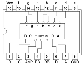
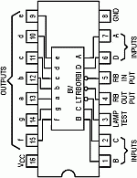
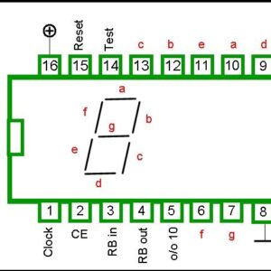
🧩 Pin Configuration (16-Pin DIP):
| Pin No. | Symbol | Description |
|---|---|---|
| 1 | a | Segment a output |
| 2 | b | Segment b output |
| 3 | c | Segment c output |
| 4 | d | Segment d output |
| 5 | e | Segment e output |
| 6 | f | Segment f output |
| 7 | g | Segment g output |
| 8 | GND | Ground |
| 9 | LT | Lamp Test (active LOW) |
| 10 | BI | Blanking Input (active LOW) |
| 11 | RBI | Ripple Blanking Input |
| 12 | D | BCD Input D (MSB) |
| 13 | C | BCD Input C |
| 14 | B | BCD Input B |
| 15 | A | BCD Input A (LSB) |
| 16 | VCC | +5V Power Supply |
This configuration ensures easy connection to standard BCD sources and 7-segment displays.
⚡ Electrical Characteristics:
-
Supply Voltage (VCC): 5V TTL standard
-
Input High Voltage (VIH): ≥ 2V
-
Input Low Voltage (VIL): ≤ 0.8V
-
Output Current (IOL): 20 mA max per segment
-
Propagation Delay: ~25 ns typical
-
Power Dissipation: ~50 mW
The open-collector design allows driving higher-voltage displays with proper external pull-up resistors, providing flexibility in display design.
🧠 How It Works:
The 7447 IC accepts a 4-bit BCD input (0000–1001) and decodes it into 7 outputs (a–g) to illuminate a common-anode 7-segment display and show digits 0–9.
-
BCD Inputs (A–D): Represent the decimal number (0–9) in binary
-
Segment Outputs (a–g): Drive the corresponding display segments
-
Active LOW Outputs: A LOW signal turns ON the segment in a common-anode configuration
-
Lamp Test (LT): Turns on all segments when LOW for display testing
-
Blanking Input (BI) and Ripple Blanking Input (RBI): Control leading-zero suppression in multiple-digit displays
This IC effectively reduces the circuit complexity by eliminating the need for multiple logic gates to drive a 7-segment display.
🛠️ Applications:
-
Digital Counters and Clocks – Display numeric values directly
-
Electronic Meters – Show readings from sensors or microcontrollers
-
Educational Projects – Teaching BCD-to-7-segment conversion
-
Embedded Systems – Simple numeric output without additional circuitry
-
Scoreboards and Digital Indicators – Drive high-voltage displays with 15V open-collector outputs
-
Test Equipment – Lamp test and blanking features for display verification
💡 Advantages:
-
Directly drives common-anode 7-segment displays
-
Supports high-voltage displays up to 15V
-
Reduces component count for BCD-to-7-segment conversion
-
TTL compatible for seamless integration with standard logic circuits
-
Includes lamp test and blanking inputs for flexible display control
📦 Package Includes:
-
1 × 7447 BCD to 7-Segment Decoder / Driver IC (DIP-16)
📘 Conclusion:
The 7447 DIP BCD to 7-Segment Decoder / Driver is a high-performance, versatile IC for digital display applications. With open-collector outputs rated for 15V, it supports high-voltage common-anode displays while simplifying circuit design. Its TTL compatibility, lamp test, and blanking features make it a trusted choice for digital counters, clocks, scoreboards, and educational projects, delivering reliable and efficient performance.




Reviews
There are no reviews yet.