4511 DIP BCD TO 7-SEGMENT LATCH DECODER DRIVER
12.00 EGP
4511 DIP BCD to 7-Segment Decoder Driver – Converts BCD input to numeric display. Ideal for counters, timers, and digital readout systems.
Description
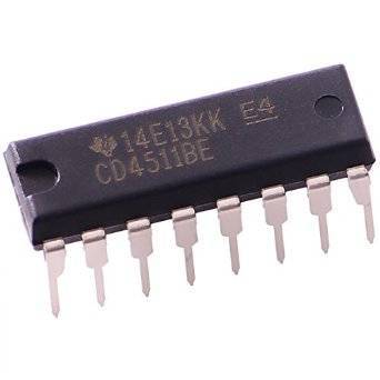
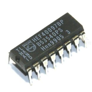
The 4511 DIP BCD to 7-Segment Latch Decoder Driver is a highly versatile and widely used CMOS logic IC designed to drive common-cathode 7-segment LED displays. It converts a 4-bit Binary-Coded Decimal (BCD) input into the corresponding decimal digit on a 7-segment display. This IC is essential for digital readout systems, counters, clocks, and calculators, providing a simple and efficient way to visually represent numeric data.
The CD4511 (or simply 4511) belongs to the 4000 CMOS series and integrates a BCD to 7-segment decoder, latch, and display driver into one compact 16-pin Dual Inline Package (DIP). It is specifically designed for common-cathode displays, where all LED segments share a common ground connection.
This IC takes binary input data (0000 to 1001) and decodes it into seven outputs (a, b, c, d, e, f, g) that drive the corresponding LED segments. Any input greater than 1001 (decimal 9) results in all segments turning off, making it perfect for decimal display applications.
Thanks to its built-in latch function, the 4511 can store data temporarily, allowing display values to remain stable even when input changes occur — a critical feature in systems requiring synchronized or multiplexed display control.
Key Features:
-
⚙️ Function: BCD to 7-segment display decoder and driver
-
💡 Display Type: Common Cathode
-
🔋 Operating Voltage Range: 3V to 15V (typical 5V or 12V)
-
⚡ High-Speed CMOS Logic: Fast response with low power consumption
-
🧠 Integrated Latch: Holds the display data until the next update
-
🔌 Seven Segment Outputs (a–g): Drives LED segments directly
-
🔥 Lamp Test Input: Allows testing of all segments simultaneously
-
🧩 Blanking Input: Turns off all segments without affecting stored data
-
🌡️ Operating Temperature Range: -55°C to +125°C
-
🧰 16-Pin DIP Package: Easy for prototyping and PCB mounting
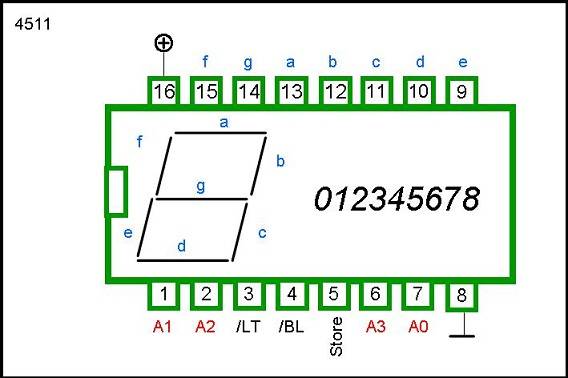
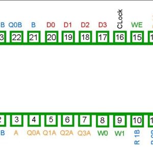
Pin Configuration:
The 4511 IC features a 16-pin Dual Inline Package (DIP), as shown below:
| Pin No. | Symbol | Function |
|---|---|---|
| 1 | B | BCD Input Bit 1 |
| 2 | C | BCD Input Bit 2 |
| 3 | LT | Lamp Test (Active Low) |
| 4 | BI | Blanking Input (Active Low) |
| 5 | LE | Latch Enable |
| 6 | D | BCD Input Bit 3 |
| 7 | A | BCD Input Bit 0 |
| 8 | GND | Ground |
| 9 | e | Segment e Output |
| 10 | d | Segment d Output |
| 11 | c | Segment c Output |
| 12 | b | Segment b Output |
| 13 | a | Segment a Output |
| 14 | g | Segment g Output |
| 15 | f | Segment f Output |
| 16 | Vcc | Power Supply (3V–15V) |
This intuitive pin layout simplifies connection to both microcontrollers and discrete digital circuits.
Functional Overview:
1. BCD to 7-Segment Decoder:
The IC converts the binary-coded decimal (BCD) inputs (A, B, C, D) into signals that light up the corresponding segments (a–g) to display digits 0 through 9.
2. Latch Enable (LE):
When LE = HIGH, the IC latches (stores) the input data. When LE = LOW, it updates the display based on the real-time input.
3. Blanking Input (BI):
When BI = LOW, all display segments are turned off, regardless of the input or latch state — useful for power-saving or multiplexing.
4. Lamp Test (LT):
When LT = LOW, all segments are turned ON to test the display.
Truth Table:
| Inputs (D C B A) | Decimal Equivalent | Display Output |
|---|---|---|
| 0000 | 0 | 0 |
| 0001 | 1 | 1 |
| 0010 | 2 | 2 |
| 0011 | 3 | 3 |
| 0100 | 4 | 4 |
| 0101 | 5 | 5 |
| 0110 | 6 | 6 |
| 0111 | 7 | 7 |
| 1000 | 8 | 8 |
| 1001 | 9 | 9 |
| 1010–1111 | Undefined | Blank |
Electrical Characteristics:
-
Supply Voltage: 3V to 15V
-
Input Logic Levels:
-
HIGH: ≥ 2V
-
LOW: ≤ 0.8V
-
-
Output Current per Segment: 20mA typical
-
Power Dissipation: 500mW max
-
Propagation Delay: 250ns typical
The IC is designed for direct LED driving (through current-limiting resistors), ensuring reliable performance even in demanding digital systems.
Applications:
The 4511 BCD to 7-Segment Driver IC is a key component in projects requiring numerical displays. It finds use in:
-
✅ Digital Counters and Clocks – Displaying numeric outputs directly from logic counters.
-
✅ Timers and Stopwatches – For displaying elapsed time values.
-
✅ Digital Voltmeters and Ammeters – To show measured values.
-
✅ Scoreboards and Meters – Ideal for numeric data presentation.
-
✅ Learning and Training Kits – Perfect for students studying digital display systems.
-
✅ Microcontroller Projects – Used with Arduino, Raspberry Pi, or PIC for numeric readouts.
Example Use Case:
Suppose you’re designing a 4-digit counter using a 74LS90 decade counter and a 4511 driver IC. Each 4511 decodes the counter output into a 7-segment display format, allowing you to visually represent numbers from 0000 to 9999 with minimal coding and hardware complexity.
This configuration is widely used in digital clocks, event counters, and instrumentation panels.
Advantages:
-
Integrates decoder, latch, and driver in one package
-
Compatible with CMOS and TTL logic levels
-
Low power consumption and high noise immunity
-
Provides stable display output with latch function
-
Easy interface with microcontrollers or BCD counters
-
Supports lamp test and blanking features
Package Includes:
-
1 × 4511 DIP BCD to 7-Segment Latch Decoder Driver IC
Conclusion:
The 4511 DIP BCD to 7-Segment Latch Decoder Driver is a compact, efficient, and feature-rich solution for driving 7-segment displays. With its integrated latch, blanking, and lamp test functions, it offers excellent control and flexibility for both beginners and professionals.
Whether you are building a digital counter, electronic scoreboard, or a learning kit, the 4511 makes display interfacing simple and efficient. Reliable, affordable, and easy to use — it’s an indispensable part of any digital display project.
Related products
-
- Out of Stock
- 40 Series
40107 DIP Dual 2-Input NAND Buffer / Driver
- 4.00 EGP
- Read more
-
Reviews
There are no reviews yet.