Rgb Led Module
10.00 EGP
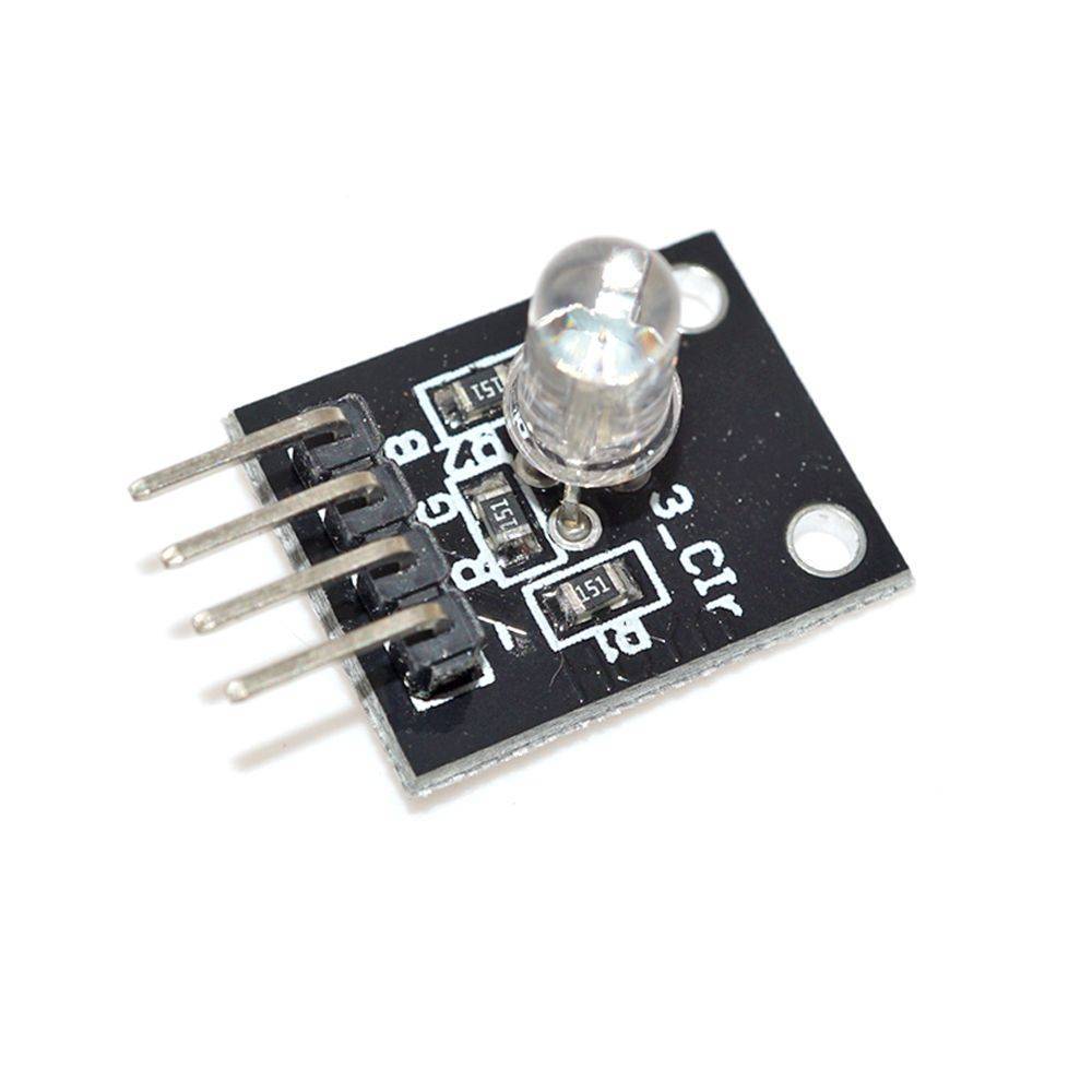
- RGB LED is a light emitting diode that displays just about any color by manipulating the intensities of either the Red, the Green or the Blue LED.
Out of stock
Description
Rgb Led Module
- RGB stands for Red, Green and Blue and these are the primary colors.
- RGB LED is a light emitting diode that displays just about any color by manipulating the intensities of either the Red, the Green or the Blue LED.
- It can produce a variety of different colors instead of seeing the individual color as the LEDs are very closed-packed inside.


- An RGB LED is composed of 3 LEDs that are connected to either a common cathode or common anode Arduino.

Common Cathode vs Common Anode RGB Arduino
- For a common cathode, all 3 LEDs are integrated to a single pin which is a negative connection and in order to control the colors, you will need to provide a DC voltage supply or a HIGH signal.
- In a Common Anode, again all 3 LEDs are connected to a pin but this time it is a positive connection.
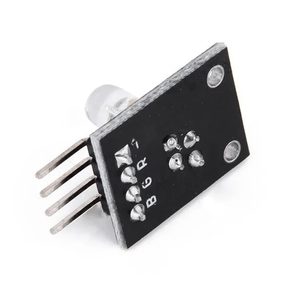
- And this is why an RGB LED has 4 pins, one for each LED and one for the common cathode or common anode. See the diagram below.

Try these other LED module projects.
- For beginners: RGB LEDs , Button Controlled LED, Potentiometer Controlled LED, LEDs with 74HC595.
- For intermediate: 2-color LED module KY-011, 3-color full-color LED SMD modules KY-009 , 2-color LED module 3MM KY-029, Automatic flashing colorful LED module KY-034
Simple Arduino RGB Circuit Diagram
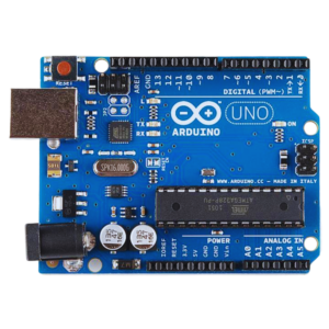
- Here is a simple project of interfacing an RGB LED module to an Arduino UNO.
- First we need to connect the wires to integrate the RGB LED module to the Arduino board and it is best that we use the same color combination of wires (red, green, blue and black) to avoid confusion.
- Place the RGB LED module on your breadboard and connect the wires according to color (but you can use any color you want). Connect the black wire to the cathode or anode pin of the module. Now, place the other end of the wire to the Arduino Pin slots.
- Red wire = 7 pin
- Green wire = 6 pin
- Blue wire = 5 pin
- Black wire = Ground

Specification:
- Material: FR4
- Length: 25mm
- Width: 11mm
- Height: 16mm
- Weight: 1.59g
- Operating Voltage: 5v DC
Code Setup
Setting up the global variables
int redPin     = 7;
int greenPin = 6;
int bluePin    = 5;
Here, we will do the void setup and we will have 3 output for this project
void setup() {
 pinMode(redPin, OUTPUT);
 pinMode(greenPin, OUTPUT);
 pinMode(bluePin, OUTPUT);
}
For the loop section, this function is for the RGB color transition and will change every second. We will make use of the setColor() function to set the redValue to 255 and 0 for the others and so on and so forth. We will also use different argument values to get different colors like white and purple.
void loop() {
 setColor(255, 0, 0);  // Red Color
 delay(1000);
 setColor(0, 255, 0);  // Green Color
 delay(1000);
 setColor(0, 0, 255);  // Blue Color
 delay(1000);
 setColor(255, 255, 255);  // White Color
 delay(1000);
 setColor(170, 0, 255);  // Purple Color
 delay(1000);
}
In this last section of the Code, the redValue, greenValue and blueValue are arguments that will indicate the intensity of the brightness of the LED’s.
void setColor(int redValue, int greenValue, int blueValue) {
 analogWrite(redPin, redValue);
 analogWrite(greenPin, greenValue);
 analogWrite(bluePin, blueValue);
}
Full Code:
Common usage of a RGB LED module
- Can be made into Indoor and outdoor lighting
- Used in mobile phones
- LCD
- Can be integrated to Automotive lights
- In order for your RGB LED module to produce a white color, you need to set the maximum brightness of the 3 LED of your project. In this article, we have set the argument values to 255 for for each LED to achieve the white color.
Package Included:
- 1 X Rgb Led Module
Additional information
| Weight | 0.00195 kg |
|---|---|
| Dimensions | 2.5 × 1.1 × 1.6 cm |



Reviews
There are no reviews yet.