7474 DIP Dual D Positive Edge Triggered Flip-Flop With Preset AND Clear
12.00 EGP
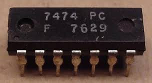
7474 Dual D Flip-Flop IC with Preset and Clear. Edge-triggered, TTL compatible, perfect for counters, registers, and digital timing circuits.
Description
The 7474 Dual D Positive Edge Triggered Flip-Flop is a fundamental integrated circuit in the 7400 TTL logic family, designed for sequential logic operations that require data storage and synchronization. Each package contains two independent D-type flip-flops, each featuring asynchronous preset and clear inputs, enabling versatile control in digital logic systems. Housed in a standard 14-pin Dual In-line Package (DIP), the 7474 is ideal for use in digital counters, data latches, registers, frequency dividers, and a variety of logic control circuits.
⚙️ Key Features:
-
Dual D Flip-Flops: Contains two independent flip-flops in one chip, allowing the design of efficient sequential logic circuits.
-
Positive Edge Triggered: Data is captured on the rising edge of the clock pulse, ensuring precise timing and predictable behavior.
-
Asynchronous Preset and Clear: Each flip-flop includes individual preset and clear inputs, providing full control over output states regardless of the clock input.
-
TTL Compatible: Fully compatible with standard TTL logic voltage levels for easy interfacing with other 7400 series ICs.
-
Standard 14-Pin DIP Package: Simple to integrate on breadboards and perfboards for prototyping and educational use.
-
High Reliability: Designed for stable operation with fast switching times and minimal propagation delay.
🧠 How It Works:
The 7474 operates as a D-type flip-flop, meaning that the output (Q) follows the input (D) only at the rising edge of the clock signal. Between clock pulses, the output remains stable, holding its previous state.
-
Preset (PR): When activated (logic LOW), the Q output is immediately set to HIGH, regardless of the clock.
-
Clear (CLR): When activated (logic LOW), the Q output is reset to LOW immediately.
-
Clock (CLK): The flip-flop captures the input data at the positive (rising) edge of the clock signal.
-
D Input: Determines the data to be stored; if D is HIGH during the clock’s rising edge, Q becomes HIGH.
This combination allows flexible control for initializing or resetting circuits, which is essential in counter initialization, synchronization, and system startup conditions.
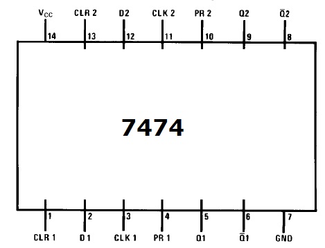
🧩 Pin Configuration:
-
1CLR – Clear (active LOW) for Flip-Flop 1
-
1D – Data Input for Flip-Flop 1
-
1CLK – Clock Input for Flip-Flop 1
-
1PR – Preset (active LOW) for Flip-Flop 1
-
1Q – Output Q for Flip-Flop 1
-
1Q’ – Complement Output Q’ for Flip-Flop 1
-
GND – Ground
-
2Q’ – Complement Output Q’ for Flip-Flop 2
-
2Q – Output Q for Flip-Flop 2
-
2PR – Preset (active LOW) for Flip-Flop 2
-
2CLK – Clock Input for Flip-Flop 2
-
2D – Data Input for Flip-Flop 2
-
2CLR – Clear (active LOW) for Flip-Flop 2
-
VCC – Power Supply (+5V typical)
⚡ Electrical Characteristics:
-
Operating Voltage: 4.75V to 5.25V (typical 5V)
-
Input High Voltage (VIH): 2.0V min
-
Input Low Voltage (VIL): 0.8V max
-
Propagation Delay: ~20ns (typical)
-
Power Dissipation: 100 mW typical per gate
-
Logic Family: TTL (Transistor-Transistor Logic)
🛠️ Applications:
-
Digital data storage and synchronization circuits
-
Clock pulse synchronization in sequential logic systems
-
Counters, frequency dividers, and shift registers
-
Microcontroller and FPGA prototyping
-
Memory latch and control signal management
-
Educational experiments in digital electronics
💡 Why Choose the 7474 DIP Flip-Flop?
The 7474 is widely regarded as one of the most reliable and easy-to-use flip-flops in the 7400 logic series. Its dual D configuration, edge-triggered operation, and independent asynchronous controls make it suitable for both simple and complex digital systems. Whether you’re designing an academic project or developing an industrial control circuit, the 7474 provides consistent and predictable logic behavior essential for timing-critical operations.
It’s also perfect for students, engineers, and hobbyists, offering an accessible way to understand the fundamentals of sequential logic, data storage, and clock synchronization.
📦 Package Includes:
-
1 x 7474 Dual D Positive Edge Triggered Flip-Flop (DIP-14)
📘 Summary:
The 7474 DIP Dual D Flip-Flop is a cornerstone logic IC for digital design, offering precise data control, robust performance, and versatile functionality. With features like asynchronous preset and clear, TTL compatibility, and edge-triggered operation, it’s a must-have component for anyone working with digital circuits.



Reviews
There are no reviews yet.