DSO138 DIY Digital Oscilloscope
1,100.00 EGP
DSO138 DIY Digital Oscilloscope Kit SMD Not Soldered 13803K Version for Measuring Waveform
Out of stock
Description
Features:
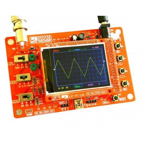
Kits using ARM Cortex-M3 processor (STM32F103C8), and includes a 2.4-inch color TFT display can be used as ARM test development board.
Available source, Capable people can be secondary development on the basis of the suite, for example, it can be changed to Millivoltmeter, data loggers, and so on (we don’t supply any technical support about that).
Circuit is simple and the kit is inexpensive
Description:
PCB size: 117 x 76mm
Screen size: 52 x 40mm
Supply voltage: DC 9V
Characteristics of indicators:
Maximum real-time sampling rate: 1Msps
Accuracy: 12Bit
Sampling buffer depth: 1024 bytes
Analog bandwidth: 0 – 200KHz
Vertical Sensitivity: 10mV / Div – 5V / Div (1-2-5 progressive manner)
Adjustable vertical displacement, and with instructions
Input impedance: 1MΩ
Maximum input voltage: 50Vpp (1: 1 probe), 400Vpp (10: 1 probe)
Coupling modes: DC / AC / GND
The horizontal time base range: 10μs / Div – 50s / Div (1-2-5 progressive manner)
- With automatic, regular and one-shot mode, easy to capture the moment waveform
- Available rising or falling edge trigger
- Adjustable trigger level position, and with instructions
- Observable previous trigger waveform (negative delay)
- Can freeze at any time waveform display (HOLD function)
- Comes 1Hz /3.3V square wave test signal source
Backage contenet:
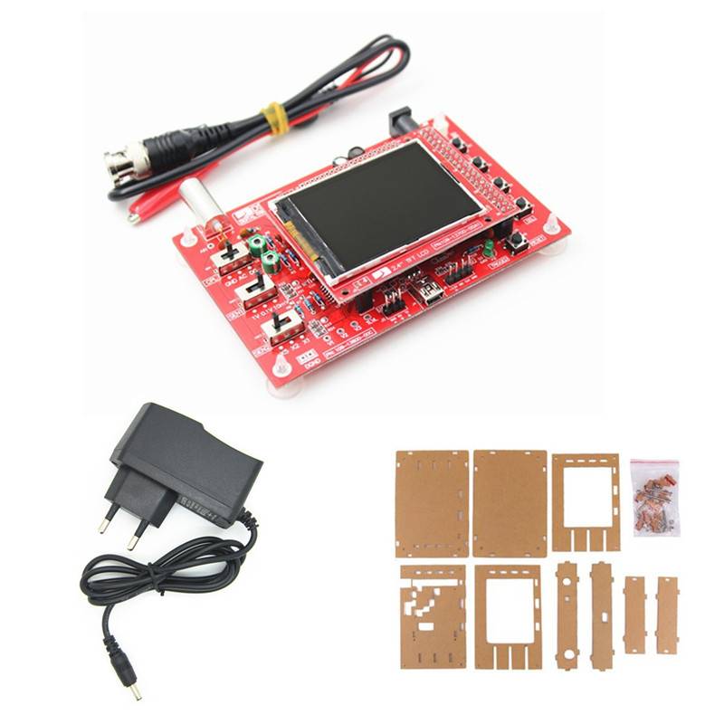
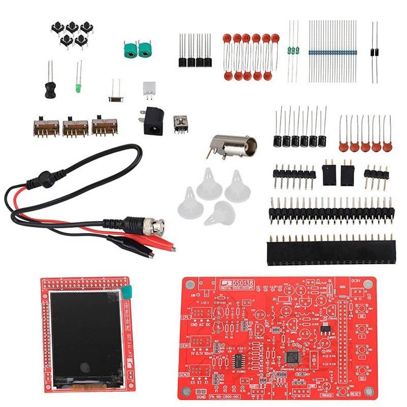
| 1 x PCB Board (SMD Soldered Version) | 40 x Resistor |
| 3 x HF-choke | 2 x Diode |
| 1 x Crystal | 1 x USB Socket |
| 5 x Tact Switch | 18 x Ceramic Capacitor |
| 1 x LED | 1 x PIN Header |
| 2 x Transistor | 2 x Regulator |
| 1 x Capacitor Trimmer | 1 x Power Indicator |
| 6 x Electrolytic Capacitor | 1 x Power Connector |
| 1 x Pin-header (Male) | 3 x Pin-header (Female) |
| 3 x Slide Switch | 1 x BNC Connector |
| 1 x LCD Screen | 1 x Connection Cable (54 / -2cm) |



Reviews
There are no reviews yet.